網頁最後修改時間:2019/01/12
 |
嗯......好的,作為每個系列的入門的第一篇,總是要來點基本知識說明 ~!@#$%^&*)(*&^%$...
想到都快寫不下去了!
還是先上個沙拉填填肚子,先來個紅外線遙控器按鍵解碼,再來把這些解碼後的按鍵名稱與數值顯示在 OLED 螢幕上;至於主菜的部分:紅外線遙控編碼協定,下一篇再來好好說說吧!
可見光的波長範圍大約在 400 nm ~ 700 nm 之間 [wiki],波長低於 400 nm 的稱為紫外線,高於 700nm 的稱為紅外線,皆為不可見光。
 |
| 電磁波譜, source: wikipedia |
 |
| 紅外線遙控器 LED 檢測 |
** 本篇網頁所涉及的紅外線遙控器,只為上圖這款。
【紅外線 (IR) 接收模組】
再來,說說 IR 接收模組,先看一下它的規格:
- 輸入電壓:DC 2.7 ~ 5.5V
- 工作電流:0.6 ~ 1.0 mA (@DC 5V)
- 接收距離:11 ~ 13 米 (依環境因素而有所變化)
- 接收角度:± 35°
- 載波頻率:37.9 kHz
- BMP 寬度:8 kHz
 |
| Typical Electrical Curves at Temp 25°, source: datasheet |
 |
| 紅外線接收模組參考電路圖 |
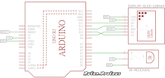
知道了怎麼確認 IR 遙控器是否動作,以及大致了解 IR 接收模組的規格之後之後,接下來就是把測試的電路接一接。
IR 接收的電路分為兩個部分:IR 接收和接收之後 16 進位解碼值與對應的按鍵值顯示。
實際接線的時候若是沒有 OLED,可以省略這部分的佈線,然後在程式中註解掉 OLED 的定義,只由 Serial 輸出即可。
 |
| 紅外線接收與顯示的接線圖 |
*********************************************************************************
【Arduino 程式說明】
程式使用 IRremote 作為 IR 發射與接收編碼和解碼的 Arduino 函式庫,下載與安裝需知如下面的說明。
/*-/--*-*/*/*/*/***//-*-*-**-*/*-*-/*/*/*-*-/-////--/**/**--**/--///--//**----**//--**//**----***//*-**//*
Arduino IRremote 函式庫下載 (選擇最新版的下載並手動安裝,或是使用 "Arduino IDE/Sketch/Manage Libraries..." 安裝)。
為了避免與原有的 Arduino 函式庫("Documents\Libraries\RobotIRremot" )造成衝突,若是安裝函式庫之後無法正常編譯,就需要移除這個函式庫;否則就不需要!
/*-/--*-*/*/*/*/***//-*-*-**-*/*-*-/*/*/*-*-/-////--/**/**--**/--///--//**----**//--**//**----***//*-**//*
IRremote 函式庫可以解碼出:送出的訊號是哪一種 IR 的通訊協定、地址(不是所有協定都有)、解碼值、解碼值的位元數數量、原始數據(raw data)、原始數據長度等......。而對於接下來的程式比較重要的關鍵資料就是解碼之後的值,有了解碼值,就可以用此作為紅外線遙控器按鍵值,而不需要先去考慮遙控器使用的是何種 IR 通訊協定,所以下面先來把這些解碼值取出來。
程式中所使用的 IR 遙控器按鍵有 17 個:數字鍵 0 ~ 9、 *、#、上下左右和一個 OK 鍵,在 Arduino IDE 選單選擇 "File/Examples/IRremote/IRrecvDemo" 修改如下,編譯並上傳。
IRemoteReceiveIRCode.ino
#include "IRremote.h"

IRrecv irrecv(4); // Receive on pin 4
decode_results results;

void setup()
{
  Serial.begin(115200);
  irrecv.enableIRIn(); // Start the receiver
  Serial.println( F("IR Receiver Ready...") );
  Serial.println();

  delay(1000);
}

void loop() {
  if (irrecv.decode(&results)) {
    Serial.println(results.value, HEX);
    irrecv.resume(); // Continue receiving
  }
}
打開 "Serial Monitor",將紅外線遙控器對準紅外線接收模組後,隨便按下幾個按鍵仔細觀察其中的數值變化,就會看到類似下圖解碼值輸出的情況。
 |
| 紅外線遙控器的按鍵解碼值 |
因為還沒有開始說明紅外線的通訊協定,所以對於使用其他紅外線遙控器進行解碼時可能會有不同的輸出。但請注意,對於本篇所使用的紅外線遙控器而言,情況就會是如此,只有按鍵解碼值可能會跟上面的輸出有所不同。
利用這樣的輸出方式,用戶可以分別得到紅外線遙控器上 17 個按鍵的解碼值。
沿用上一個程式並且加入了按鍵值判斷和 OLED 的支援(函式庫下載1、下載2),只要按鍵值被有效解碼,OLED 螢幕左上角會出現解碼值、中間部分會出現對應的紅外線遙控器按鍵值,如下圖所示。
 |
| 紅外線遙控器解碼值與按鍵值顯示在 OLED |
 |
| Serial Monitor 的輸出畫面 |
其中 IRKeyDecode() 函式裡面的按鍵值可以根據實際得到的按鍵解碼值輸入,即便是相同的遙控器也有可能產生出不同的解碼值,所以這裡只列出測試時所使用的遙控器所解出的按鍵解碼值,其餘的部分請再自行補上。
若沒有使用到 OLED,記得要將程式第一行 OLED 定義註解掉,否則程式會執行不了!
範例程式碼下載
/*-/--*-*/*/*/*/***//-*-*-**-*/*-*-/*/*/*-*-/-////--/**/**--**/--///--//**----**//--**//**----***//*-**//*
有購買商品的使用者,網頁中所需相關資料已放置於雲端硬碟,請自行下載使用! 其餘的使用者,請自行依照提供之連結下載相關資料,程式碼複製貼上使用!
/*-/--*-*/*/*/*/***//-*-*-**-*/*-*-/*/*/*-*-/-////--/**/**--**/--///--//**----**//--**//**----***//*-**//*
【補充:ESP8266 紅外線接收】
紅外線特別常與 WiFi 模組互相配合使用,所以為了後面同一系列的網頁補充了這一小節。
上面介紹的 IRremote 並不太適合作為 ESP8266 的 Arduino 函式庫,而改用其原本的其他函式庫分支,請自行下載安裝。
/*-/--*-*/*/*/*/***//-*-*-**-*/*-*-/*/*/*-*-/-////--/**/**--**/--///--//**----**//--**//**----***//*-**//*
Arduino IRremoteESP8266 函式庫下載 (選擇最新版的下載並手動安裝,或是使用 "Arduino IDE/Sketch/Manage Libraries..." 安裝)。
/*-/--*-*/*/*/*/***//-*-*-**-*/*-*-/*/*/*-*-/-////--/**/**--**/--///--//**----**//--**//**----***//*-**//*
打開函式庫的範例程式 "File / Examples / IRremoteESP8266 / IRecvDemo" ,修改第 26 行 (這樣修改後,可讓所有的 ESP8266 模組都可以使用)
IRrecvDemo.ino
1 2 3 4 5 6 7 8 9 10 11 12 13 14 15 16 17 18 19 20 21 22 23 24 25 26 27 28 29 30 31 32 33 34 35 36 37 38 39 40 41 42 43 44 45 46 47 48 49 50 | /* * IRremoteESP8266: IRrecvDemo - demonstrates receiving IR codes with IRrecv * This is very simple teaching code to show you how to use the library. * If you are trying to decode your Infra-Red remote(s) for later replay, * use the IRrecvDumpV2.ino example code instead of this. * An IR detector/demodulator must be connected to the input kRecvPin. * Copyright 2009 Ken Shirriff, http://arcfn.com * Example circuit diagram: * https://github.com/markszabo/IRremoteESP8266/wiki#ir-receiving * Changes: * Version 0.2 June, 2017 * Changed GPIO pin to the same as other examples. * Used our own method for printing a uint64_t. * Changed the baud rate to 115200. * Version 0.1 Sept, 2015 * Based on Ken Shirriff's IrsendDemo Version 0.1 July, 2009 */ #ifndef UNIT_TEST #include <Arduino.h> #endif #include <IRutils.h> // An IR detector/demodulator is connected to GPIO pin 14(D5 on a NodeMCU // board). const uint16_t kRecvPin = 2; // 改為 GPIO 2 IRrecv irrecv(kRecvPin); decode_results results; void setup() { Serial.begin(115200); irrecv.enableIRIn(); // Start the receiver while (!Serial) // Wait for the serial connection to be establised. delay(50); Serial.println(); Serial.print("IRrecvDemo is now running and waiting for IR message on Pin "); Serial.println(kRecvPin); } void loop() { if (irrecv.decode(&results)) { // print() & println() can't handle printing long longs. (uint64_t) serialPrintUint64(results.value, HEX); Serial.println(""); irrecv.resume(); // Receive the next value } delay(100); } |
編譯上傳後打開 Serial Monitor,拿出套件裡的紅外線遙控器(或是其他形式的),對準接收模組就可得到類似下面的輸出。
 |
| ESP8266, Arduino Serial Monitor 的輸出畫面 |
【結論】
雖然紅外線遙控不如無線遙控的距離來的遠,但是卻是一般家電(電視、DVD 播放器、機上盒等......)最常用的遙控設備,為了在操作時不互相影響,幾乎每一個廠家都有自己的紅外線通訊協定。
進行測試的時候,可以觀察按下按鍵的時間長短,對於接收模組上的 LED 燈和程式解碼輸出的狀態影響為何 ? 只有當接收模組上的 LED 燈只閃一下,輸出才會是實際的按鍵解碼值;超過一下,輸出表示的是按鍵值持續被按下的解碼值,一但了解這種狀況,才不會在解碼其他紅外線遙控器時採用到此值。
下一篇,將會深入紅外線通訊協定,舉一、兩個廠家來作例子,說明它們的紅外線遙控器訊號編碼到底為何?只有瞭解這些東西,當談論到直接使用原生數據發送紅外線訊號時,才能真正了解到解碼值是怎麼由原生數據計算而來。
<< 部落格相關文章 >>
沒有留言:
張貼留言
留言屬名為"Unknown"或"不明"的用戶,大多這樣的留言都會直接被刪除掉,不會得到任何回覆!
發問問題,請描述清楚你(妳)的問題,別人回答前不會想去 "猜" 問題是什麼?
不知道怎麼發問,請看 [公告] 部落格提問須知 - 如何問問題 !