網頁最後修改時間:2021/09/10
ESP32-CAM 二維碼辨識之門鎖控制(下面簡稱 ESP32QRDoorLock)的主要週邊裝置包括:攝像頭(不在本篇討論)、門磁(磁簧)開關、WS2812B和電磁鎖與其驅動模組。
本篇是該主題系列的第二篇,內容是關於這些週邊裝置如何用 ESP32-CAM 做控制的說明,有:
- (00)簡介
- (01)參考接線
- (02)參考程式碼
- (02-01)WS2812B 全彩 LED 驅動
- (02-02)電磁鎖驅動
- (02-03)門磁開關訊號接收
- (02-04)接腳與函式初始化
- (02-05)外部裝置功能測試函式
- (02-06)完整程式碼與實測影片
- (03)結論
/*-/--*-*/*/*/*/***//-*-*-**-*/*-*-/*/*/*-*-/-////--/**/**--**/--///--//**----**//--**//**----***//*-**//*
** 本篇內容都是搭配 ESP32-CAM 燒錄與接腳擴充二合一底板 (下文簡稱底板)所進行的測試,參數設定不一定適用於其他的搭配!
/*-/--*-*/*/*/*/***//-*-*-**-*/*-*-/*/*/*-*-/-////--/**/**--**/--///--//**----**//--**//**----***//*-**//*
【(00)簡介】
ESP32-CAM 因為另外搭配了記憶卡和攝像頭的緣故,其實能用的接腳所剩無幾,若想要外接週邊裝置時,其實有點難度!但若考慮捨棄不用記憶卡,則可空出這些接腳另作他用。不過也因為這幾個記憶卡用的接腳或多或少在電路上都有再經過設計,因此在外接週邊裝置到 ESP32-CAM 上時,參考電路圖或是其文件的說明就顯得非常重要,避免不能用而多走了冤枉路!
** 關於 ESP32-CAM 開發板說明書、電路圖和其他資料,請上下面網址去下載。
【(01)參考接線】
電磁鎖(<DOORLOCK>)和 WS2812B 全彩 LED(<RGBLED>)要選用 ESP32-CAM 上可作為輸出的接腳;門磁(磁簧)開關(<LIMITSWITCH>)要選用 ESP32-CAM 上可作為輸入的接腳,至於到底要用哪三個?請參照 ESP32-CAM 電路圖再自己選擇。
底板上的每個接腳都附有 <+5V> 和 <GND> 的電源接腳對,所以請參考下圖來接線即可。
【(02)參考程式碼】
程式碼是以 x01_ESP32CamOTAProgramming.ino 為基礎,額外再加入驅動和測試的程式部分所組成。
/*--*//**---/*///**---*-*////***--*/*///***----*///--*/*///**--*/*//**--**/*//
*(02-01)WS2812B 全彩 LED 驅動:
WS2812B 全彩 LED 驅動的部分,採用比較有名的函式庫 FastLED,所以需要在程式裡開頭處引入它的標頭檔
16 17 18 |
#include <Arduino.h> #include <WiFi.h> #include <FastLED.h> |
接著,在下面宣告幾個會用到的全局變數。
首先,記得要先把選好的接腳號碼取代掉 #1 和 #2
31 32 33 34 35 36 |
/*================== FASTLED =================*/ const int NUM_LEDS = #1; // 填入 LED 的數量取代 #1 const uint8_t DATA_PIN = #2; // 填入 WS2812 通訊接腳號碼取代 #2 // 定義 LED 陣列 CRGB ws2812[NUM_LEDS]; |
然後再定義幾個常用的顏色,和一個測試會用到的儲放顏色的陣列。
65 66 67 68 69 70 71 72 73 74 75 76 77 78 79 80 |
/*================== FASTLED =================*/ // Colors definition for WS2812 #define BLACK CRGB ( 0, 0 , 0) // Black #define WHITE CRGB (255, 255, 255) // White #define RED CRGB (255, 0, 0) // Red #define ORANGE CRGB (255, 127, 0) // Orange #define YELLOW CRGB (255, 255, 0) // Yellow #define GREEN CRGB ( 0, 255, 0) // Green #define BLUE CRGB ( 0, 0, 255) // Blue #define INDIGO CRGB ( 0, 255, 255) #define VIOLET CRGB (127, 0, 255) // Violet CRGB x02_colors[9] = { RED, ORANGE, YELLOW, GREEN, BLUE, INDIGO, VIOLET, WHITE, BLACK }; |
預先宣告 blink () 函式,避免編譯時出現找不到該函式的錯誤。
84 |
void blink (const int8_t blink_count, const TickType_t delay, const CRGB color); |
撰寫 blink () 函式的主程式。
112 113 114 115 116 117 118 119 120 121 122 123 124 125 126 127 128 129 130 131 |
/**======================================================================== ** blink() *? 系統運行狀態的指示 *@param blink_count const int8_t *@param color CRGB *========================================================================**/ void blink (const int8_t blink_count, // 閃爍次數 const CRGB color) // WS2812 顏色 { uint8_t state = LOW; for (int x = 0; x < (blink_count << 1); ++x) { if (state ^= HIGH) { ws2812[0] = color; } else { ws2812[0] = BLACK; } FastLED.show(); delay (50); } } |
ESP32QRDoorLock 預設只使用一顆 WS2812B 全彩 LED。以現有的硬體配置,是可以直接用 PC 的 USB 埠來做整體的供電,不會有所問題!
不過一但確定要增加 LED 的數量,那麼當電流不足以供給整體電路電流消耗的話,就有可能會導致整個系統重置或是崩潰。所以如果出現這種非正常程式運作的情況導致的系統重置,請先使用預設數量的 LED 進行測試,確定是電源導致的問題後,再考慮外加電源給 WS2812B。
FastLED 提供不少的 LED 燈色變化,不過在 ESP32QRDoorLock 只使用來做閃爍和顏色的變化而已,如果看倌有需要可以再自行做變化。
/*--*//**---/*///**---*-*////***--*/*///***----*///--*/*///**--*/*//**--**/*//
*(02-02)電磁鎖驅動:
電磁鎖就像是繼電器一樣,不能使用 GPIO 直接驅動,需要外接驅動模組才不至於損壞 GPIO,而且也才能保證有足夠的電流驅動電磁鎖。
ESP32QRDoorLock 所採用的電磁鎖是屬於彈簧自動回歸式的。觸發時,電磁鎖頭會縮回,門屬於會自動彈出的設計會自然開啟;非觸發時,電磁鎖頭會自動彈出,由於電磁鎖頭是一個滑頭形狀,此時就可以用手動的方式將門關回,會自動鎖住。所以設計上,必須確保電磁鎖頭有足夠的觸發時間讓門彈出。
首先,宣告和定義幾個需要的全局變數,記得要先把選好的接腳號碼取代掉 #3
45 46 47 |
/*================== GPIO =================*/ /** 電磁鎖 */ const uint8_t DOORLOCK = #3; // 填入電磁鎖驅動模組控制接腳號碼取代 #3 |
接著就可以撰寫門鎖控制的程式。
這部分的程式預期要用於電動鎖和電磁鎖兩種鎖頭,不過現只實現電磁鎖一種,使用時只要填入 false 做引數就可以。
133
134
135
136 137 138 139 140 141 142 143 144 145 146 147 148 |
/**======================================================================== ** doorControl() *? 門鎖開關控制 *@param isMotor const bool * 門鎖的形式。true: DC Motor; false: 電磁開關 *========================================================================**/ void doorControl (const bool isMotor) { if (isMotor) { // 如果使用電動鎖頭,寫程式在這裡 // ... } else { digitalWrite (DOORLOCK, HIGH); delay (1000); digitalWrite (DOORLOCK, LOW); } } |
/*--*//**---/*///**---*-*////***--*/*///***----*///--*/*///**--*/*//**--**/*//
*(02-03)門磁開關訊號接收:
門磁裡面內嵌有一個磁簧開關,沒有磁性物體靠近時是開路的狀態,反之就是閉路。為了要能得知它的狀態,要選擇 ESP32-CAM 可以做為輸入且能上拉的接腳。
首先,宣告和定義幾個需要的全局變數,記得要先把選好的接腳號碼取代掉 #4
48 49 50 51 52 53 |
/** 門磁(磁簧)開關 */ const uint8_t LIMITSWITCH = #4; // 填入門磁開關訊號接接腳號碼取代 #4 // 門的狀態 #define OPEN HIGH #define CLOSE LOW #define dDoorState digitalRead(LIMITSWITCH) |
門磁訊號的接收可以使用輪詢或是中斷的方式來取得,但對於這個例子來說,採用中斷服務會比較適合。
另外,開關在閉合的時候會發生訊號抖動的情形,容易造成重複觸發誤動作,這樣的情形可用硬體電路或軟體程式的方式來去除抖動訊號;對於這個例子來說,採用軟體程式比較方便。
首先,宣告幾個中斷服務函式會用到的全局變數。
55 56 57 |
/*================== lsInterrupt =================*/ volatile bool bIntTrigger = false; unsigned long ulLastMicros; |
接著,建立 ESP32 中斷服務函式。
門磁開關的去抖動時間設定為 150ms。不同的開關會有不同的抖動時間,要依實際情況適當地做調整,才能正確的取得穩定的訊號。
在取得穩定的訊號之後,會設定一個旗標並且解除中斷服務函式。中斷服務函式只有在需要的時候才會由程式裡做啟動,一但完成後就會自動被解除。
100 101 102 103 104 105 106 107 108 109 110 |
/**======================================================================== ** lsInterrupt() *? 中斷處理函式 *========================================================================**/ void IRAM_ATTR lsInterrupt () { if((long)(micros() - ulLastMicros) >= 150000L) { bIntTrigger = true; detachInterrupt (digitalPinToInterrupt(LIMITSWITCH)); } ulLastMicros = micros(); } |
/*--*//**---/*///**---*-*////***--*/*///***----*///--*/*///**--*/*//**--**/*//
*(02-04)接腳與函式初始化:
根據之前所討論關於接腳的使用,初始化接腳和函式庫,並關閉 LED。
86 87 88 89 90 91 92 93 94 95 96 97 98 |
/**======================================================================== ** ioInit() *? ESP32 接腳和 FastLED 初始化 *========================================================================**/ void ioInit () { pinMode (DOORLOCK, OUTPUT); digitalWrite (DOORLOCK, LOW); pinMode (LIMITSWITCH, INPUT_PULLUP); FastLED.addLeds<WS2812B, DATA_PIN, GRB>(ws2812, NUM_LEDS); //* 開機關閉 LED ws2812[0] = BLACK; FastLED.show (); } |
/*--*//**---/*///**---*-*////***--*/*///***----*///--*/*///**--*/*//**--**/*//
*(02-05)外部裝置功能測試函式:
藉由使用者的輸入,決定要測試的外部裝置。
191 192 193 194 195 196 197 198 199 200 201 202 203 204 205 206 207 208 209 210 211 212 213 214 |
/**======================================================================== ** x02_functionTest *? 選擇外部裝置功能測試 *========================================================================**/ void x02_functionTest () { if (Serial.available()) { char c = Serial.read (); switch (c) { case 0x31: Serial.print (F("Test LED, ")); x02_testLED (); Serial.println (F("done.")); break; case 0x32: Serial.print (F("Test Door Lock/Unlock")); x02_testDoorLockUnlock (); Serial.println (F("done.")); break; default: return; } Serial.println (F("Enter 1 for LED test, 2 for door Lock/Unlock test")); } } |
選擇 1,依序閃爍顯示 x02_colors[] 陣列裡面的顏色。
150
151
152
153
154
155
156
157
158
159 |
/**======================================================================== ** testLED *? 顏色顯示測試 *========================================================================**/ void x02_testLED () { for (int i = 0; i < 9; i++) { blink (5, x02_colors[i]); delay (1450); } } |
選擇 2,發送門開啟的訊號並等待門被開啟;門一但確認開啟後,閃綠燈且啟用中斷服務函式;等待門被關閉且中斷旗標被設置,閃紅燈且完成開關門測試。
161 162 163 164 165 166 167 168 169 170 171 172 173 174 175 176 177 178 179 180 181 182 183 184 185 186 187 188 189 |
/**======================================================================== ** x02_testDoorLockUnlock *? 開關門測試 *========================================================================**/ void x02_testDoorLockUnlock () { Serial.print (F("Check door status, ")); if (dDoorState == OPEN) { Serial.println(F("OPEN\nCLOSE DOOR TRY AGAIN!\n\n")); return; } Serial.println (F("CLOSE")); Serial.println (F("01-Open the door")); doorControl (false); // 等待門開啟(要移開門磁開關) while (dDoorState == CLOSE); // 亮燈表示門已開啟 blink (5, GREEN); Serial.println (F("02-Sets an interrupt for external pin")); // 啟用中斷服務函式 attachInterrupt ( digitalPinToInterrupt (LIMITSWITCH), lsInterrupt, FALLING ); Serial.println (F("03-Waiting for door close")); while (dDoorState == OPEN || bIntTrigger == false); blink (5, RED); Serial.print (F("04-Closed the door, ")); } |
/*--*//**---/*///**---*-*////***--*/*///***----*///--*/*///**--*/*//**--**/*//
*(02-06)完整程式碼與實測影片:
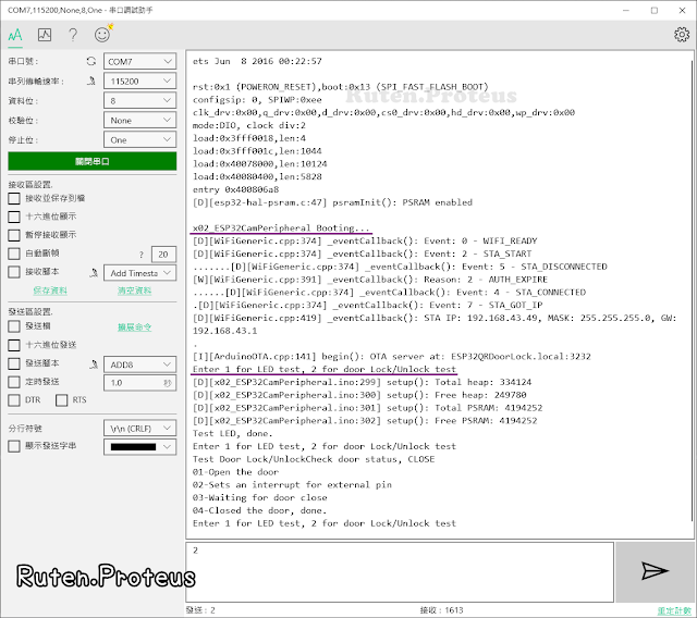
以 x01_ESP32CamOTAProgramming.ino 為基礎加入上面所說的部份,將 ioInit () 新增到 setup () 中,x02_functionTest () 新增到 loop () 中,就完成整個程式,請新增一個 Arduino IDE 檔案並儲存下面程式碼為 x02_ESP32CamPeripheral
編譯並上傳之後,實際測試的輸出與影片。
【(03)結論】
ESP32-CAM 開發板可以利用捨棄記憶卡的功能取得多支可用的接腳,但由於電路設計的關係會被侷限住,因此在使用前請先參考電路圖再選用。若在使用的過程中出現問題,建議先上網路尋找是否有相同問題的解決方法,再試著自己解決。
為了避免程式陷入無窮循環以及方便多任務的安排,下一篇要來看看怎麼把 Watchdog 加入到程式中,以及加入 Watchdog 之後對原本程式的影響和其衍生問題解決的方法。
.
.
<<部落格相關文章>>
.
.


沒有留言:
張貼留言
留言屬名為"Unknown"或"不明"的用戶,大多這樣的留言都會直接被刪除掉,不會得到任何回覆!
發問問題,請描述清楚你(妳)的問題,別人回答前不會想去 "猜" 問題是什麼?
不知道怎麼發問,請看 [公告] 部落格提問須知 - 如何問問題 !